CMS:Number One Crossbar Switch

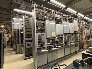
The Number One Crossbar Switch (1XB) is from the Vermont/Kenwood central office on N 65th St in Seattle. After 1957, these offices were renamed to Lakeview, and this machine in particular was renamed to Lakeview 2-3. It is the only remaining operational 1XB.
Installation and Service Life
The Vermont 1XB was originally cut over on March 1 1942. Over 100 Western Electric workers worked to build the switch, which replaced the Vermont/Kenwood manual office that had served the residential neighborhoods around the University of Washington up to that point. [citation needed]
Initially cut over with 15,908 stations, it grew over its lifetime as the number of subscribers in the neighborhood increased. A point of interest for the museum is that our founder, Herb H. Warrick, Jr. was a switchman in this office in its early years.
The machine was retired in the early 1980s, and selected frames were brought to the museum and re-assembled into a functioning switch.
Museum Life
The 1XB was assembled in the museum by volunteers Les Anderson and others. Originally envisioned to be in very limited service, only the minimum amount of equipment was wired up, and until 2019, the switch could only place a maximum of two concurrent calls. This was in part because the volunteers did not contemplate a full working central office, and in part because much of the most important wiring for the machine was cut during its removal. This included the wiring for the Originating Marker route relay bays and ground supplies, which effectively rendered the switch unusable, except for a few very specific operations that it could perform. In addition, it could not originally terminate calls from the museum's Panel Switch, as the equipment needed to do that was removed in the early 1970s, when the last of the Seattle panels were retired.
In 2016 volunteers Sarah Autumn and æstrid Smith learned that some No. 1 Crossbar equipment was available from collector Jim Day in his warehouse in West Haven, CT. This equipment had been salvaged from the Coney Island 6 exchange on Avenue U in Brooklyn, NY. Sarah and æstrid traveled to West Haven and retrieved two SD-25013-01 Full Selector terminating senders, and one SD-25012-01 subscriber's sender, which were driven back to Seattle in a minivan. Volunteers Les Anderson, Colin Slater, æstrid Smith and Sarah Autumn installed the terminating senders in 2017, and made the first phone call to the 1XB from the Panel in the same year. In the following years, three more terminating senders, and two more subscriber senders were brought back from Jim Day's warehouse to Seattle and installed in the machine.
In 2019-2021 the switch underwent major rewiring and upgrades. This work was performed entirely by Sarah Autumn, much of it during the 2020 COVID-19 pandemic. These upgrades were a major overhaul that required taking the switch out of service for a long period of time. Effectively rebuilding the entire machine's topology from scratch, this work increased the call capacity of the 1XB to its theoretical maximum, and fully integrated it with the other switches in the museum, and with our Asterisk box kercheep, and the call simulator.
Notable Equipment
The 1XB has the following notable equipment, in addition to the common frames that would be expected in any similar No. 1 Crossbar office:
- CARW frame, for distributing air raid warnings to the public
- Tandem Crossbar "ring marker"
- 10- and 100-line concentrating frames
- Line Insulation Test frame
- ANI frames
- Both old and new-style subscriber's senders
- Recorded Announcement frame from a Crossbar Tandem
- Kercheep, the computer, and various digital and carrier equipment
Trunking
The 1XB has a complex trunking pattern that includes both first-choice and alternate routes. It also decides on call routing via class of service based on which sender is serving your call. This pattern is possibly the most complex and diverse of any of the museum's switches. Trunks include, but are not limited to:
- to itself via MF (832)
- to itself via RP (833)
- to itself via 2600hz E-signaling units (834)
- to itself via RP through the panel office tandem (524)
- to the Panel (722)
- to the 5XB (232)
- to the panel via the office tandem (365)
- to the Audichron (844)
- to Kercheep, with ANI/CAMA (537)
- to the 3ESS (830)
- to the DMS-10 via kercheep
Technical Information
The configuration of the No. 1 Crossbar at the museum is minimal, when compared to its active service life. The switch has one of the following of each frame:
Aisle 4
- Line Link Frame (LLF)
- Subscriber Sender Link (SSL)
- District Junctor (DJ) - containing 100 junctors
- District Link (DL)
- Office Link (OL)
- Incoming Trunk Test Connector
- Incoming Link (IL)
- Incoming Trunk (100 trunks)
- Terminating Sender Link (TSL)
- Number Group Connector (NGC)
- Line Junctor Connector (LJC)
- Terminating Sender Frame (3 MF, 2 FS term senders, total of 5)
- Sender Selector equipment
- Recorded announcement frame
Aisle 3
- Line Distributing Frame (LDF)
- Originating Marker (OM)
- Originating Marker Connector (OMC)
- Subscriber Sender (2x SD-27810-01, 3x SD-25012-01, total of 5 senders)
- Misc RR
- Office Junctor Grouping Frame (OJGF)
- ANI Trouble Ticketer
- Block Relay Frame (BRF 0)
- ANI Number Network Primary (ANI NN)
- ANI Trunk Frame (ANI T)
- ANI Outpulser (ANI OP)
- ANI Identifier
- Service Observing Equipment (SOJ)
- Terminating Marker
- Terminating Marker Connector
- 100 Line Concentrator
Aisle 2
- 10 Line Concentrator
- Line Insulation Test (LIT)
- MF Current Supply (MFCS)
- Permanent Signal Holding Trunks
- Originating Sender Test Relay Rack
- Office Interrupter (OI)
- Floor Alarm (FLA 100)
- Emergency Alarm
- CARW Equipment (2 bays)
- Intercepting and Announcement equipment
- Call Data Transmitter (CDT)
- Billing Data Transmitter (BDT)
- Tandem Crossbar Ring Marker
Aisle 1 (Test Aisle)
- ANI Identifier-Outpulse and Trunk Test Frame (ANI TST)
- Incoming Trunk Test Frame (ITT)
- Terminating Sender Test Frame (TST)
- Terminating Trouble Indicator (TTI)
- Originating Trouble Indicator (OTI)
- Outgoing Trunk Test Frame (OGT)
- Outgoing Trunk Test jack panel (OGT JK)
- Sender Make Busy Frame (SMB)
- Originating Sender Test Frame (OST)
- District Junctor Test Frame (DJ TST)
