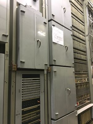
Decoder

A decoder is a circuit in the panel switching system that acts as a type of routing table. It accepts input from a sender in the form of a 3-digit office code, and returns a set of instructions that tells the sender how to route the call towards its destination office[1]. Each call must be routed individually so there is one decoder operation per call. An average-sized panel office usually had three decoders, though up to six could be provisioned if traffic volume warranted it.
The holding time for a decoder is about 300 milliseconds. During this time, it accepts input from the sender, validates the integrity of the sending and receiving leads, performs the translation, and then returns the results to the sender, again checking the validity of the data before releasing itself to serve another request. If a decoder found itself in error, it timed out, and sent a trouble release signal to the sender that was connected to it. It then copied its current state to a decoder trouble indicator, so a switchman could observe and diagnose the failure.
In later crossbar switching systems, the decoder evolved into a marker.
