CMS:Panel Switch: Difference between revisions
Intcreator (talk | contribs) No edit summary |
No edit summary |
||
| (One intermediate revision by the same user not shown) | |||
| Line 1: | Line 1: | ||
[[File:Panel Switch.jpg|thumb|The Panel switch with the OutGoing Trunk (OGT) test desk on the left and various frames on the right]] | [[File:Panel Switch.jpg|thumb|The Panel switch with the OutGoing Trunk (OGT) test desk on the left, and various frames on the right]] | ||
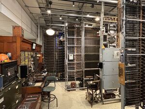
The '''[[wikipedia:Panel_switch|Panel Switch]]''' was in service at the Rainier/Parkway exchange in Seattle from 1923-1974. The museum's Panel switch installation is an collection of a small fraction of components of the original switch, which was around eight times larger. | The '''[[wikipedia:Panel_switch|Panel Switch]]''' was in service at the Rainier/Parkway exchange in Seattle from 1923-1974. The museum's Panel switch installation is an collection of a small fraction of components of the original switch, which was around eight times larger. | ||
== History == | == History == | ||
The Panel switch was installed in the Rainier/Parkway central office from 1921-1923 at the cost of approximately $294,000 ({{Inflation|US|start_year=1923|value=294,000|fmt=eq}}). Starting at 12 AM on March 3, 1923, it provided the first dial service to Seattle. On its opening day, it had approximately 4,000 lines connected and 36,199 originating calls were made from the switch. | The Panel switch was installed in the Rainier/Parkway central office from 1921-1923 at the cost of approximately $294,000 ({{Inflation|US|start_year=1923|value=294,000|fmt=eq}}). Starting at 12:00 AM on March 3, 1923, it provided the first dial service to Seattle. On its opening day, it had approximately 4,000 lines connected and 36,199 originating calls were made from the switch. | ||
In 1974 the Panel switch was decommissioned. | In 1974, the Panel switch was decommissioned and its lines and trunks were cut over to a 1ESS. Unusually, the switch was left entirely in place after being shut down, because its wiring in the cable trays was mixed with other wiring that was still in use and the central office engineers were worried that severing the wires would cause a service outage. | ||
[[File:Parkway removing frames.png|thumb|Removing a panel frame from Parkway in 1988. ]] | |||
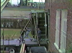
In 1986 frames were selected to be transferred to the [[CMS:Connections Museum|Connections Museum]], and on November 3 1987, the frames were removed from Parkway and brought to the museum on a large flatbed truck in multiple trips. Notably, since the panel was built inside the Parkway office, an exterior window had to be removed from the building to extract the frames, as there were no doors large enough. | |||
In | == Museum Life == | ||
[[File:Parkway 1965 layout.jpg|thumb|The Panel switch's layout in the Parkway Central Office in 1965. Pink sections denote the components of the Panel switch currently installed in the museum.]] | The panel was assembled at the museum by Emery Schaffer and Norm Christiansen, with the help of other volunteers. In its original configuration, they got just enough wired up to place two to four concurrent phone calls. In the early 2000s-2010s, it was cared for by Chuck Huffington. | ||
When Sarah arrived at the museum in 2014, she took on the care of the panel switch as a her main project. Over the course of several years, she re-wired all of the inter-frame wiring, and rebuilt the network topology. Sarah brought up the Office selector frame, Automatic Routine Test frames, and brought many existing frames to full or near-fully working order. She is now the primary maintainer of the panel switch, and is considered to be the last remaining expert on the topic. | |||
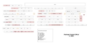
Two frames, the [[Floor Alarm Board]], and District Coin Control frame were added from Don Capehart in 2019. [[File:Parkway 1965 layout.jpg|thumb|The Panel switch's layout in the Parkway Central Office in 1965. Pink sections denote the components of the Panel switch currently installed in the museum.]] | |||
== Configuration == | == Configuration == | ||
=== Central Office === | === Central Office === | ||
This configuration is as of 1965. | The configuration of the office changed over its lifetime. This configuration is as of 1965. | ||
'''Number of Line Finder Frames:''' 12 | '''Number of [[Line Finder]] Frames:''' 12 | ||
* 6 old-style 300-point | * 6 old-style 300-point | ||
* 6 new-style 400-point | * 6 new-style 400-point | ||
'''Number of District Frames:''' 9 | '''Number of [[District Selector (frame)|District]] Frames:''' 9 | ||
'''Number of Office Frames:''' 3 (post-1957) | '''Number of [[Office Selector (frame)|Office]] Frames:''' 3 (post-1957) | ||
'''Number of Senders:''' 72, in 8 frames (post-1956) | '''Number of [[Sender|Senders]]:''' 72, in 8 frames (post-1956) | ||
* 56 non-coin | * 56 non-coin | ||
| Line 30: | Line 36: | ||
* 47, in 10 frames (pre-1956) | * 47, in 10 frames (pre-1956) | ||
'''Number of Decoders:''' 3 | '''Number of [[Decoder|Decoders]]:''' 3 | ||
* Each decoder operated in ⅓ second, thus one decoder could serve 12,000 originating calls per hour without a bottleneck, assuming call volume was steady. | * Each decoder operated in ⅓ second, thus one decoder could serve a maximum of 12,000 originating calls per hour without a bottleneck, assuming call volume was steady. | ||
* Altogether, 3 decoders could serve a theoretical max of 36,000 originating calls per hour. | * Altogether, 3 decoders could serve a theoretical max of 36,000 originating calls per hour. | ||
* | * In practice the call volume varied throughout the day, and would have been capped by other factors, not the decoders. | ||
'''Number of Incoming Frames''': 10 | '''Number of [[Incoming Selector (frame)|Incoming]] Frames''': 10 | ||
* 60 selectors per frame. Total of 600 selectors. | * 60 selectors per frame. Total of 600 selectors. | ||
* Theoretical max of 600 concurrent inbound calls, however it could not get this high in practice, due to the fact that incoming trunks were not evenly distributed, and the number of selectors on the final frame limited the number of calls that could be connected to a subscriber’s telephone. | * Theoretical max of 600 concurrent inbound calls, however it could not get this high in practice, due to the fact that incoming trunks were not evenly distributed, and the number of selectors on the final frame limited the number of calls that could be connected to a subscriber’s telephone. | ||
'''Number of Final Frames''': 11 | '''Number of [[Final Selector (Frame)|Final]] Frames''': 11 | ||
* 480 available final selectors / 10,000 line capacity | * 480 available final selectors / 10,000 line capacity | ||
=== Museum Configuration === | === Museum Configuration === | ||
'''Number of Line Finder Frames:''' | '''Number of Line Finder Frames:''' 1 | ||
'''Number of | '''Number of District Frames: 1''' | ||
'''Number of | '''Number of Office Frames: 1''' | ||
'''Number of Senders:''' 6, non-coin | |||
'''Number of Decoders:''' | '''Number of Decoders: 1''' | ||
'''Number of Incoming Frames''': | '''Number of Incoming Frames''': 1 | ||
'''Number of Final Frames''': | '''Number of Final Frames''': 1 | ||
=== Auxiliary Equipment === | === Auxiliary Equipment === | ||
* OGT Desk* | * [[Trouble Desk|OGT Desk]]* | ||
* Tea Carts* | * [[Tea Cart|Tea Carts]]* | ||
* #12 Local Test Desks* | * #12 Local Test Desks* | ||
* Chief Switchman’s Desk | * Chief Switchman’s Desk | ||
| Line 73: | Line 77: | ||
* Sender Test Frame* | * Sender Test Frame* | ||
* Stuck Sender/District Finder* | * Stuck Sender/District Finder* | ||
* Resistance lamp | * Resistance lamp rack* | ||
* District and Incoming coil racks | * District and Incoming coil racks | ||
* A & B Operator Boards | * A & B Operator Boards | ||
| Line 82: | Line 86: | ||
* Call Through Test Set* | * Call Through Test Set* | ||
* MDF & IDF* | * MDF & IDF* | ||
* | * 301 Type Power/BDFB board* | ||
* Gas-powered Generators | * Gas-powered Generators | ||
* Batteries | * Batteries | ||
Latest revision as of 09:17, 24 February 2025

The Panel Switch was in service at the Rainier/Parkway exchange in Seattle from 1923-1974. The museum's Panel switch installation is an collection of a small fraction of components of the original switch, which was around eight times larger.
History
The Panel switch was installed in the Rainier/Parkway central office from 1921-1923 at the cost of approximately $294,000 (equivalent to $5,257,547 in 2023). Starting at 12:00 AM on March 3, 1923, it provided the first dial service to Seattle. On its opening day, it had approximately 4,000 lines connected and 36,199 originating calls were made from the switch.
In 1974, the Panel switch was decommissioned and its lines and trunks were cut over to a 1ESS. Unusually, the switch was left entirely in place after being shut down, because its wiring in the cable trays was mixed with other wiring that was still in use and the central office engineers were worried that severing the wires would cause a service outage.

In 1986 frames were selected to be transferred to the Connections Museum, and on November 3 1987, the frames were removed from Parkway and brought to the museum on a large flatbed truck in multiple trips. Notably, since the panel was built inside the Parkway office, an exterior window had to be removed from the building to extract the frames, as there were no doors large enough.
Museum Life
The panel was assembled at the museum by Emery Schaffer and Norm Christiansen, with the help of other volunteers. In its original configuration, they got just enough wired up to place two to four concurrent phone calls. In the early 2000s-2010s, it was cared for by Chuck Huffington.
When Sarah arrived at the museum in 2014, she took on the care of the panel switch as a her main project. Over the course of several years, she re-wired all of the inter-frame wiring, and rebuilt the network topology. Sarah brought up the Office selector frame, Automatic Routine Test frames, and brought many existing frames to full or near-fully working order. She is now the primary maintainer of the panel switch, and is considered to be the last remaining expert on the topic.
Two frames, the Floor Alarm Board, and District Coin Control frame were added from Don Capehart in 2019.

Configuration
Central Office
The configuration of the office changed over its lifetime. This configuration is as of 1965.
Number of Line Finder Frames: 12
- 6 old-style 300-point
- 6 new-style 400-point
Number of District Frames: 9
Number of Office Frames: 3 (post-1957)
Number of Senders: 72, in 8 frames (post-1956)
- 56 non-coin
- 16 coin
- 47, in 10 frames (pre-1956)
Number of Decoders: 3
- Each decoder operated in ⅓ second, thus one decoder could serve a maximum of 12,000 originating calls per hour without a bottleneck, assuming call volume was steady.
- Altogether, 3 decoders could serve a theoretical max of 36,000 originating calls per hour.
- In practice the call volume varied throughout the day, and would have been capped by other factors, not the decoders.
Number of Incoming Frames: 10
- 60 selectors per frame. Total of 600 selectors.
- Theoretical max of 600 concurrent inbound calls, however it could not get this high in practice, due to the fact that incoming trunks were not evenly distributed, and the number of selectors on the final frame limited the number of calls that could be connected to a subscriber’s telephone.
Number of Final Frames: 11
- 480 available final selectors / 10,000 line capacity
Museum Configuration
Number of Line Finder Frames: 1
Number of District Frames: 1
Number of Office Frames: 1
Number of Senders: 6, non-coin
Number of Decoders: 1
Number of Incoming Frames: 1
Number of Final Frames: 1
Auxiliary Equipment
- OGT Desk*
- Tea Carts*
- #12 Local Test Desks*
- Chief Switchman’s Desk
- Automatic Routine Selector Test Frame*
- Decoder Test Frame*
- Decoder Trouble Indicator*
- Sender Test Frame*
- Stuck Sender/District Finder*
- Resistance lamp rack*
- District and Incoming coil racks
- A & B Operator Boards
- A & B Operator Test Boards
- Trunk Finder Frames*
- Interrupter Frames*
- Miscellaneous Relay Frames*
- Call Through Test Set*
- MDF & IDF*
- 301 Type Power/BDFB board*
- Gas-powered Generators
- Batteries
- Ringing Plant & Tone Supplies
- 2-Party District control frame*
- Message Register Cabinets*
- ~100 duplex motors running continuously*
- Floor Alarm Board 201♰
- District Coin Control frame♰
* indicates equipment that is on display at museum
♰ indicates equipment donated by Don Capehart in 2019
Statistics
Average normal daily load (1923): 13,000
